Table of Contents
Biology, Electronics, Aesthetics, and Mechanics
See also Robot Building, Robot Design and Category Robotics.
A design philosophy for robotics, where analogue electronics and reactive sensor control is preferred over digital electronics, microcontrollers or the use of planning AI. BEAM is the invention of robotics physicist Mark Tilden.
Freeforming, Recycling and the use of Solar Power
A key element of BEAM is the use of 'freeforming' circuits rather than using a conventional substrate upon which to build a circuit, such as a PCB. Components are directly soldered together and become part, or the entirety of the structure of the robot. BEAMer's also prefer to use recycled parts and material in the construction of their robots, and the use of solar power rather than batteries.
These design restrictions result in some beautifully simple and effective machines.
BEAM Nervous Networks
The control mechanism of a BEAM robot is a set of analogue circuits which are broadly biologically inspired, and can be connected together to provide fixed control signals (for tasks such as moving a multi-legged walker) or have sensors integrated into them to provide a link to the outside world. There is a distinctive language developed for the construction of these circuits, which I'll attempt to explain a bit of below.
Nv Neuron

One of the simplest BEAM components is the nv neuron, which consists of a capacitor, resistor and inverter arranged so they form a 1st order high pass filter with it's output inverted. In BEAM robotics, circuits are considered active when the output is low - this circuit will output low pulses for a constant time (set by the values of the capacitor and resistor) when the input changes voltage.

An Nv neuron in the breadboard with a large capacitor, to make the pulse easier for a human to see. The inverter is provided by the 7404 hex inverter, which contains 6 logical NOT gates that we subvert for non-digital means.
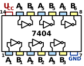
Schematic of the 7404
Nv Neuron Array/Grounded Bicore
Nv neurons can be stacked together in arrays, where signals will be propagated slowly along them.

With a simple modification, the output of the second Nv neuron can be fed into the input of the first. This forms a simple oscillator - what BEAM robot builders refer to as a grounded bicore.
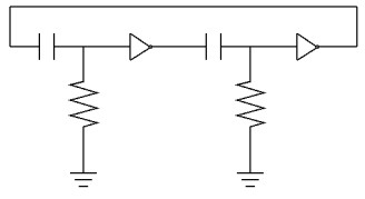

These bicores are the workhorses of BEAM robot brains, and are used to provide oscillating signals which can be controlled from other Nv neurons, or directly from sensor input.
Suspended Bicore
With some modifications, it's possible to greatly simplify the grounded bicore into the following form:


By playing with the values of the components, different oscillation patterns can be made.
Solar Engines
The power coming from a solar cell is pretty tiny. In order to do anything much, especially drive a motor, you need to employ some method for increasing the current from the solar panel. The commonest method in BEAM robotics is to store the energy in a capacitor and use it in bursts. This circuit is called a solar engine.
FLED Solar Engine

The LED is a flashing type, and is used for detecting when the voltage across the capacitor reaches around 2v - then it turns on and trips the transistor into dumping all the power to the motor. The bigger the capacitor, the more charge it will store. This method is known as a FLED Solar engine.
Movement for free! (Well, using a desk lamp on a dull winters day like today…)
1381 Solar Engine
A more efficient method is to use a voltage regulator, such as the 1381 - unfortunately they are difficult to get hold of, and I couldn't manage to get any voltage regulators I had to work.
Timed Solar Engine
Another method is to just have a timer waiting a set time for the capacitor to charge. This can be useful if that fits the application better, but it's less efficient than the methods above, as you need some power to run the timer. I tried this with a 555 IC, but the power coming from the solar cell was insufficient to run the timing chip. It might be possible with a 7555 - the low power cmos version of the 555 timer.
BEAM types
Photovores
Links
- Mark Tilden's robots: http://www.beam-online.com/Robots/Galleria_other/tilden.html
- Some more example robots: http://www.xs4all.nl/~sbolt/e-index.html
- For more detail, go to the BEAM wiki: http://www.beam-wiki.org/wiki/Main_Page
- Solarbotics is the BEAM community server: http://www.solarbotics.net/
- The BEAM web ring: http://v.webring.com/hub?ring=beamring